Sensorimotor Exploration Lab: Hand Writing Robot for Experimentation and Physical Rehab
Overcoming challenges to make a robotic scribe
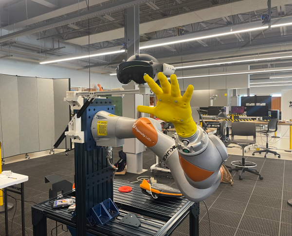
I was lucky enough to work part time at the Sensorimotor Exploration Lab during my junior year. They have a Kinova Gen 3 Ultralightweight Arm and gave me the opportunity to work on a project to make the robot write words. The project was for a research experiment designed to answer the question: what is the most effective method to learn to write new words? Participants were given 4 different modes of learning to write new words; seeing a word statically, seeing a word be written out, seeing a word and then writing it, and being guided through the motion by a robot (my part). The results we found showed that seeing a word then writing it gave the best memory performance in a follow up test 30 minutes later. Being guided by a robot gave the second best results, seeing the word be written was third, and seeing a static word was fourth. The conclusion from this experiment is that the physical act of writing words enhances learning, and that employing motor skills to complete physical acts also enhances learning.
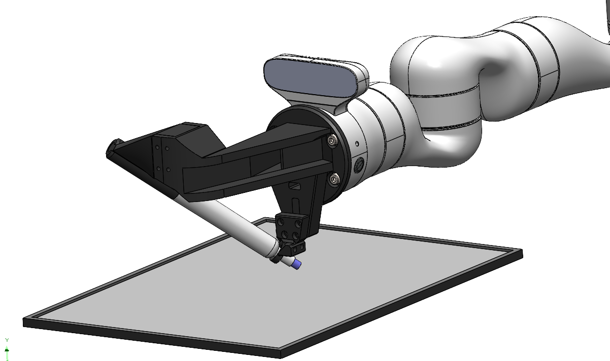
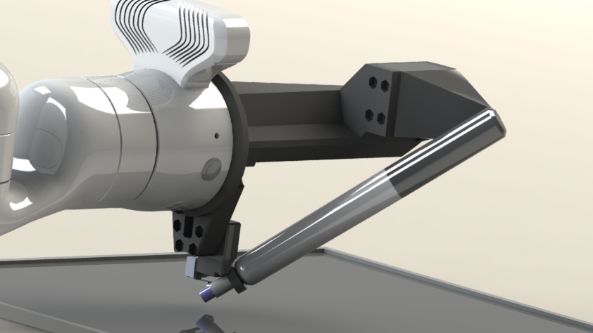
The end effector is designed for you to grasp on to a whiteboard marker and be guided through a handwriting motion
Technical Challenges
1. Manipulator Controls
My project was to fix the issues with a previous group of engineer’s capstone project to get the robot writing. The problem with their implementation was that the robot appeared jittery when writing. This made the written results look bad and was unsuitable for any experiments. In this video you can kind of see the end effector vibrating when moving up and down.
Prior team’s work to get a demo going
I tracked down the problem to the inverse kinematics algorithm that was being used. It was a real-time implementation apart of Kinova’s built in cpp API. Kinova’s built in IK solver has been known to give jerky outputs because its not desiged to be a high-performance, numerically optimal IK controller. It uses the robot’s built in CPU for its computes and is good for fast, approximate IK lookups – but when used for realtime trajectory processing it creates discontinuities/noise.
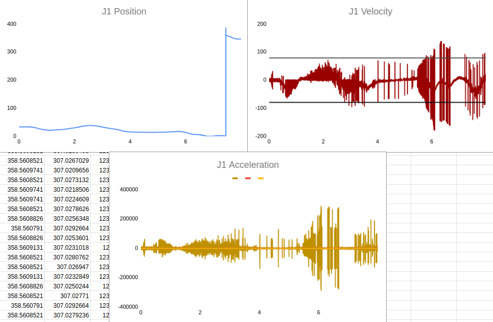
 When we tracked the robot’s trajectory using its encoders, we saw well out-of-bound and noisy kinematic profiles
The challenge then became writing a continuous inverse-kinematic algorithm that could be used for trajectory generation when given cartesian coordinates.
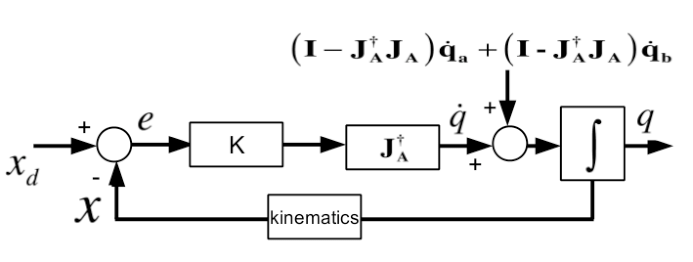
I had a kinematics library available to me from my prof Matt Pan’s time at Disney Research, so I had some options at my disposal. I used the pseudo-inverse Jacobian method to generate smooth trajectories before runtime. The way it works is basically by taking current joint angles, performing forward kinematics to get current position, calculating the difference between the current position and the target position, and using the Jacobian to convert the cartesian difference into joint space difference and applying that joint space difference to the robot’s current joints. This procedure is repeated three to four times until the euclidian error between the algorithm’s solved position and target position is small.
In simple terms, this algorithm keeps taking educated guesses as to where it should move, mathematically moves there, until it evetually ends up in the right spot.
 X is subtracted from Xd until e is neglibile, then we know q has converged!
I implemented this method over my holiday break and so I couldn’t physically verify my code. Thank god for simulation, though. My strategy was to compare the inverse kinematic results from MATLAB Simulink’s built-in-tool to my C++ based implementation. If, for the same joint inputs I was getting the same cartesian outputs, it means that my IK was working!
I was able to get a CAD model of the Kinova arm I was using. I found a tutorial for how to export the model from Solidworks into MATLAB Simulink here.
MATLAB takes your physical CAD model and converts it into a use-able simulator. It generates the transforms between linkages automatically using your Solidworks mates and allows you to input joint angles and output cartesian coordinates.
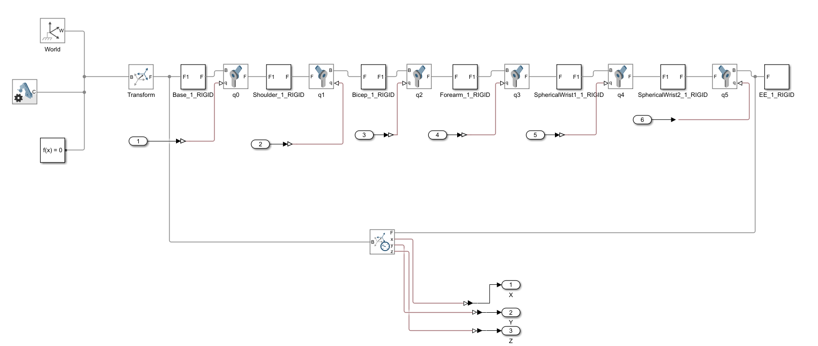
 Kinematic Model that MATLAB automatically makes using Solidworks mates
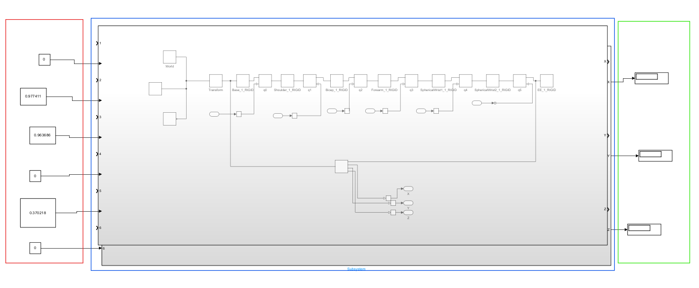
 In red on the left I input joint positions (degrees) to the kinematic model (blue) and I get cartesian coordinates (green) on the right
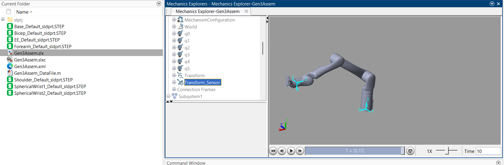
 Aside from doing the inverse kinematics for you, Simulink also gives you a 3D representation of the manipulator pose. It was really cool to see the model moving around for different joint inputs.
After a bit of messing around with home positions of joint angles in simulation, I was able to feed poses into my inverse kinematics algorithm, get joint angles back, and feed those joint angles into MATLAB Simulink, and get the original pose that I fed in back. This meant that my inverse kinematics was working!
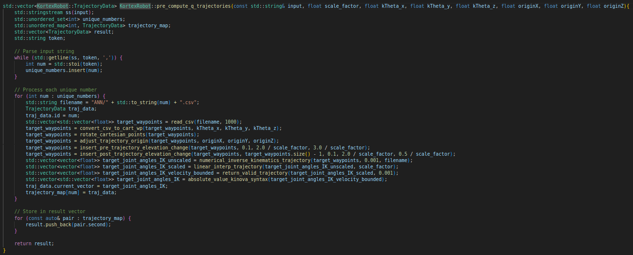
I then began working on a fully fledged trajectory generator given an array of cartesian positions. The trajectories I got were from a CODAMotion camera sensor, which provide 400Hz timestamped cartesian positions of a camera-tracked object. The function starts by taking in a csv of the trajectory points, transforming them so they start in the same spot, adding elevation changes so the manipulator moves down/up until it touches/leaves the surface, performing IK (this algo also accounts for singularities and discontinuities due to non-invertible Jacobians or position error non-convergence in finite number of iterations), adding a speed factor (linear interpolation) to slow down the trajectory (since Coda goes at 400Hz but Kinova runs at 1kHz so Kinova would try and run through points 2.5x faster), ensuring joint are within accel. and velocity limits using differentiation and adjusting the syntax to command joints to Kinova.

Since I added velocity and acceleration limiting I was confident that I could asynchronously command the positions at each new timestep (1ms) to the robot and not have it lag behind. I basically had to trust Kinova’s onboard controller to go to the position I commanded it to and allow for its internal actuator controls to get it there in 1ms. Even it it lagged behind it wasn’t by much and we got good results.
The last piece of the puzzle was making the code accessible to people who don’t have a coding background. I use made a lot of parameters accessible from a json file that allow the user to choose what trajectories they want to run, at what speed, etc…
2. End Effector
I wanted to improve the end effector to be more ergnonomic and maintain proper contact with the whiteboard/table. To do this I designed an end effector in Solidworks. The pen can move along its axis and is spring loaded. This way, the robot can be controlled to press into the table and consistently press out ink.

Learnings & Takeaways
I learned a lot about cobots, trajectory control and working in academia during my time at the Sensorimotor Exploration Lab. I owe many thanks to Dr. Manson and Dr. Pan for the opportunity and to Obi for being easy to work with. Looking forward to the future!!
 Union and University and the Kin building where I worked (right)

Related albums
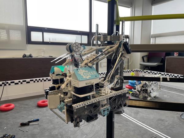
VEX Robotics Worlds 2025: Managing Complexity in Mechanical Design
9 photos
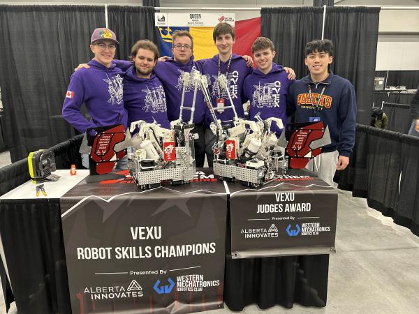
VEX Robotics Qualification 2025: Striving for Consistency
7 photos
Ingenuity Labs: Characterizing VR Headset Performance with Cobots
6 photos